Floor Plan Symbols Gridlines

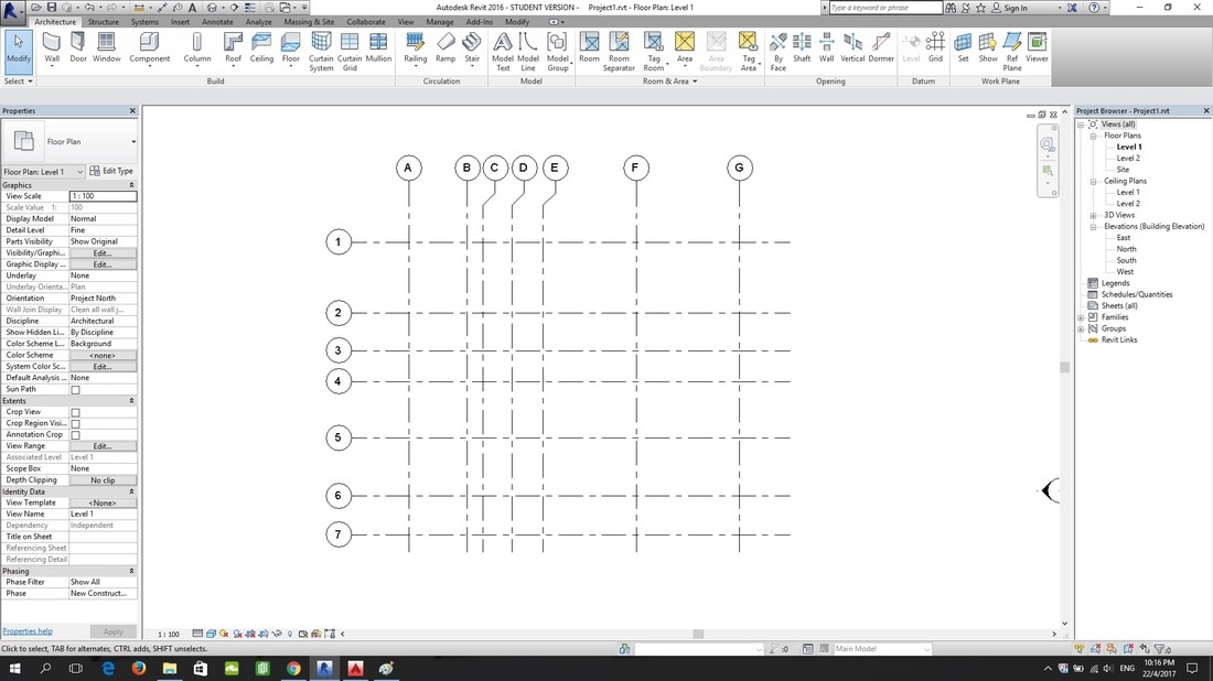
How To Create Column Grid Of The Building Autocad Architecture Blog Grid Architecture Autocad Create Floor Plan

Grid Line An Overview Sciencedirect Topics
Basic Blueprint Reading
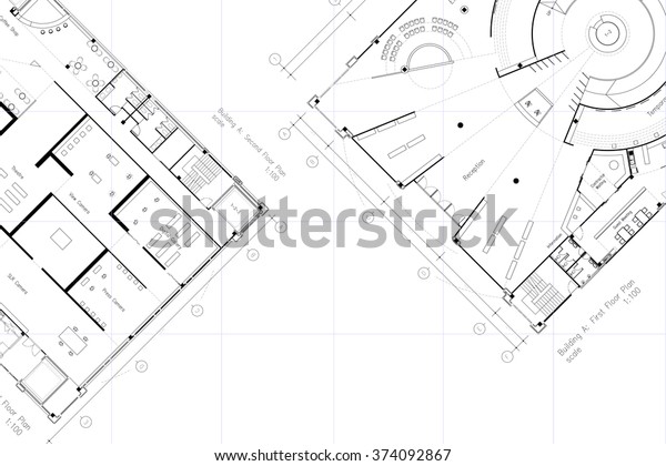
Architectural Layout Floor Plan Grid Lines Stock Illustration 374092867
Building In Modelling Architecture Life Since 2015

How To Get Missing Revit Grid Or Level Lines Back Micrographics
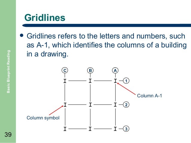
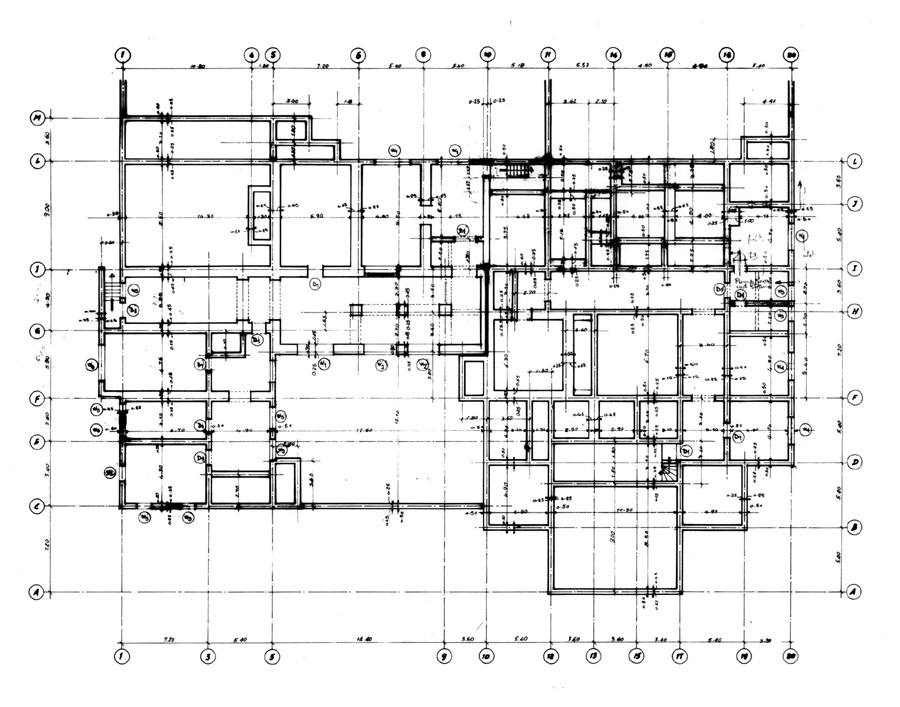
The grid consists of numbers along one axis and letters of the alphabet along the other so that one can easily pinpoint a specific column such as d.
Floor plan symbols gridlines.
Floor Plan Designing Buildings Wiki

Reading Drawings Josh Brincko
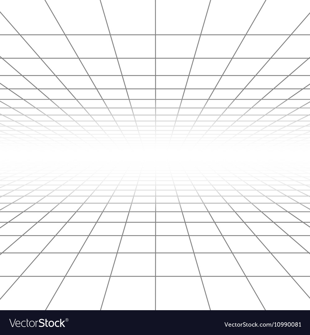
Ceiling And Floor Perspective Grid Lines Vector Image

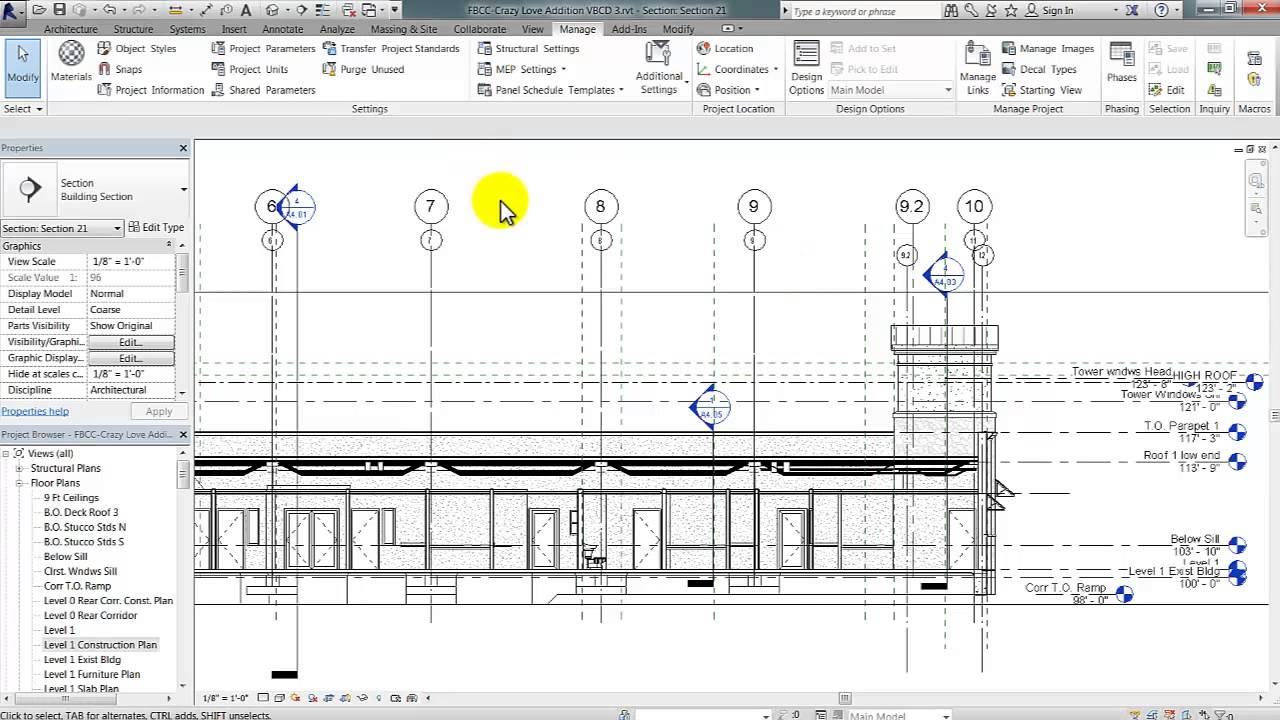
Grid Line With Gap In Revit Youtube

Grids Revit Products 2019 Autodesk Knowledge Network
Https Www Gsa Gov Cdnstatic Did Review Guide Final Pdf

How To Re Size Grid Head In Revit Architecture Youtube

Work In Progress Bim Wip

2 Nd Floor Plan And Gridlines For Transfer Beam And Column Locations Download Scientific Diagram
Hiding A Linked Model S Levels And Grids In Revit Best Cad Tips

Datum Elements Learning Revit Online
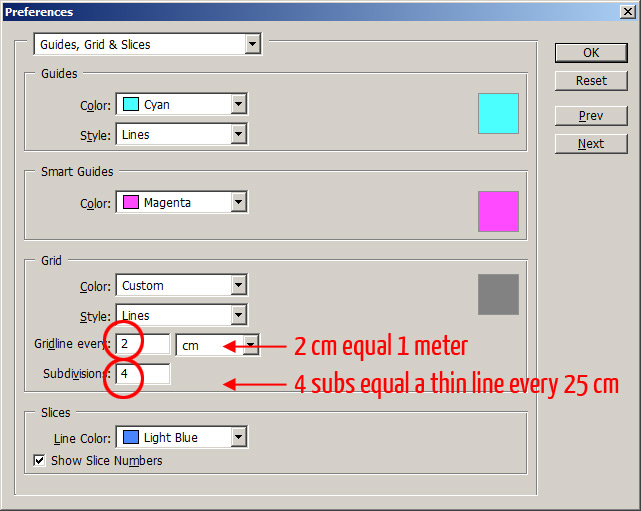
Tutorial Rotate And Scale A Scanned Floor Plan In Adobe Photoshop Plan Symbols
How To Set The Grid
Video Add Grid Lines Revit Products 2019 Autodesk Knowledge Network

Measured Grids Arcgis Pro Documentation

How To Create Grid Lines And Raft Foundation Zwcad Architecture 2017 Youtube

Revit Customizing Grid Line Symbol And Grid Head Families Youtube
Nqrkyahdv6isnm
Https Encrypted Tbn0 Gstatic Com Images Q Tbn 3aand9gcss1q81rh1sj6yvxkuohwptz902ix8xmwjo43peoxc1hiuxcb J Usqp Cau
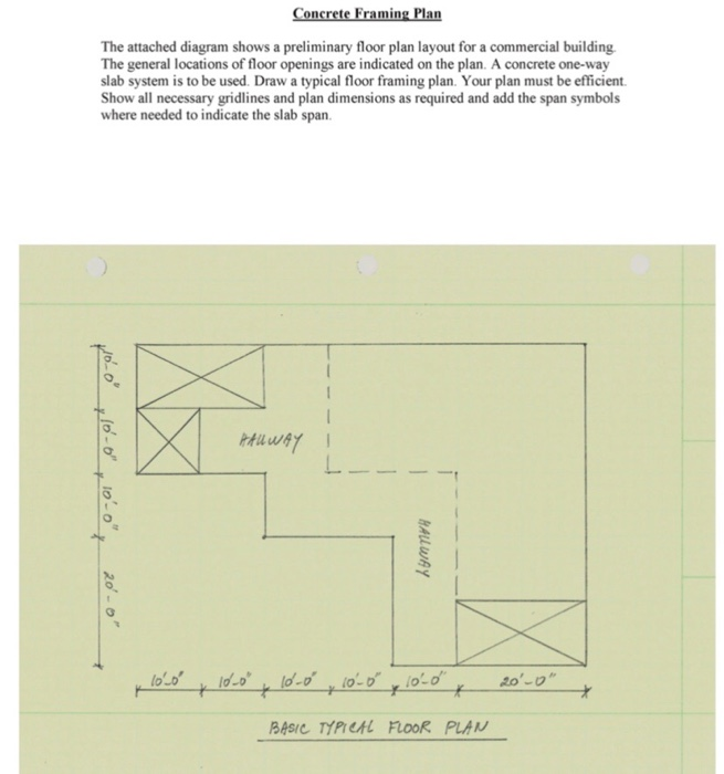
Solved Concrete Framing Plan The Attached Diagram Shows A Chegg Com

Ram Modeler Tutorial Ram Staad Opentower Wiki Ram Staad Opentower Bentley Communities

Show And Hide Grid Bubbles Revit Products 2018 Autodesk Knowledge Network
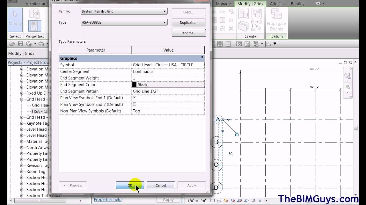
Revit Customizing Grid Line Symbol And Grid Head Families Cadtechseminars Com Youtube
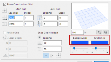
Set Window Background And Grid Line Color User Guide Page Graphisoft Help Center
Source : pinterest.com
